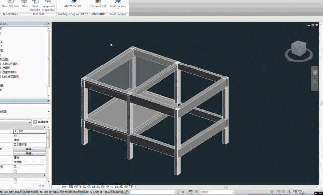
[摘要] Naviswork与桌子家的云浏览器都有比较友好的三维测量工具,但Revit中想在三维中测量两个物体之间的距离的时候实在是麻烦,于是想到通过二
Naviswork与桌子家的云浏览器都有比较友好的三维测量工具,但Revit中想在三维中测量两个物体之间的距离的时候实在是麻烦,于是想到通过二次开发来解决这个问题。
Revit的Api中有一个ReferenceIntersector类,可以在三维视图中通过一个点及一个向量找到相交的几何实体。思路上便是通过这个类实现简单的三维测量,首先需要用户点选一个实体上的点,默认的测量方向为向上,如果选择的点的主体是一个平面,则通过选择的点及平面的法向量进行测量,若果找到第二点则生成模型线并弹窗显示距离。
值得注意的有以下几个地方:
首先构造ReferenceIntersector的时候需要用一个过滤器把选择点的主体给过滤出去,要不然找到的元素就是主体本身,距离为0;
第二个要注意的就是要考虑在链接模型的图元上进行测量,因为链接模型的图元无法简单的通过Reference获取几何面,需要通过读取几何信息来获取面;
第三个就是可载入族也需要通过获取几何信息的方式来获取几何面,通过Reference获取的面会是族类型的几何面;
最后,开始我是用面的IsInside方法来判断几何实体中与点相交的面,但一些情况下会出现判断错面的问题,于是最后我是通过点到面的距离为0来取得相交面的。

以下代码:
public Result Execute(ExternalCommandData commandData, ref string message, ElementSet elements) { UIDocument uidoc = commandData.Application.ActiveUIDocument; Document doc = uidoc.Document; //选择一点 Reference ref_point = uidoc.Selection.PickObject(Autodesk.Revit.UI.Selection.ObjectType.PointOnElement); XYZ point1 = ref_point.GlobalPoint; //射线方向及工作平面法向量 XYZ rayDirection = XYZ.BasisZ; XYZ skVector = XYZ.BasisX; //当选择的主体为平面时,射线根据选择的点与此面的法线方向进行放射 if (ref_point.ElementReferenceType == ElementReferenceType.REFERENCE_TYPE_SURFACE) { PlanarFace pFace = null; //主体是链接的图元时获取平面的方法 if (ref_point.LinkedElementId.IntegerValue != -1) { RevitLinkInstance linkIns = doc.GetElement(ref_point) as RevitLinkInstance; Document linkDoc = linkIns.GetLinkDocument(); Element linkElem = linkDoc.GetElement(ref_point.LinkedElementId); Options opt = new Options(); opt.DetailLevel = ViewDetailLevel.Fine; GeometryElement geomElem = linkElem.get_Geometry(opt); pFace = GetTarFace(geomElem, point1); } else { //判断是否FamilyInstance类型的族,采用不同的获取方法 Element elem = doc.GetElement(ref_point); if (elem is FamilyInstance) { Options opt = new Options(); opt.DetailLevel = ViewDetailLevel.Fine; GeometryElement ge = elem.get_Geometry(opt); pFace = GetTarFace(ge, point1); } else { pFace = elem.GetGeometryObjectFromReference(ref_point) as PlanarFace; } } //修正射线方向及工作平面法向量 if (pFace != null) { rayDirection = pFace.FaceNormal; skVector = pFace.XVector; } } //视图 View3D v3d = doc.ActiveView as View3D; //创建射线测量出第二点 ExclusionFilter filter = new ExclusionFilter(new ElementId[] { ref_point.ElementId, ref_point.LinkedElementId }); ReferenceIntersector refIntersector = new ReferenceIntersector(filter, FindReferenceTarget.All, v3d); refIntersector.FindReferencesInRevitLinks = true; ReferenceWithContext rwc = refIntersector.FindNearest(point1, rayDirection); if (rwc != null) { XYZ point2 = rwc.GetReference().GlobalPoint; //创建模型线 Line line = Line.CreateBound(point1, point2); TaskDialog.Show("距离", Math.Round(UnitUtils.ConvertFromInternalUnits(line.Length, DisplayUnitType.DUT_MILLIMETERS), 2).ToString()); using (Transaction tran = new Transaction(doc,"尺寸")) { tran.Start(); SketchPlane sk = SketchPlane.Create(doc, commandData.Application.Application.Create.NewPlane(skVector, point1)); ModelCurve modelCurve = doc.Create.NewModelCurve(line, sk); tran.Commit(); } } else { TaskDialog.Show("返回结果","未检测到图元"); } return Result.Succeeded; } /// <summary> /// 获得与UV点相交的面 /// </summary> /// <param name="geometryElement"></param> /// <param name="uvPoint"></param> /// <returns></returns> PlanarFace GetTarFace(GeometryElement geometryElement,XYZ point) { PlanarFace face = null; foreach(GeometryObject geomObj in geometryElement) { Solid solid = geomObj as Solid; if (solid != null && solid.Faces.Size > 0) { foreach(Face f in solid.Faces) { PlanarFace pFace = f as PlanarFace; if (pFace != null) { try { if (Math.Round(pFace.Project(point).Distance, 2) == 0) { face = pFace; break; } } catch { continue; } } } } if (face != null) { break; } } if (face == null) { foreach(GeometryObject geomObj in geometryElement) { GeometryInstance geomIns = geomObj as GeometryInstance; if (geomIns != null) { face = GetTarFace(geomIns.GetInstanceGeometry(), point); } } } return face; }


